Start with the signal
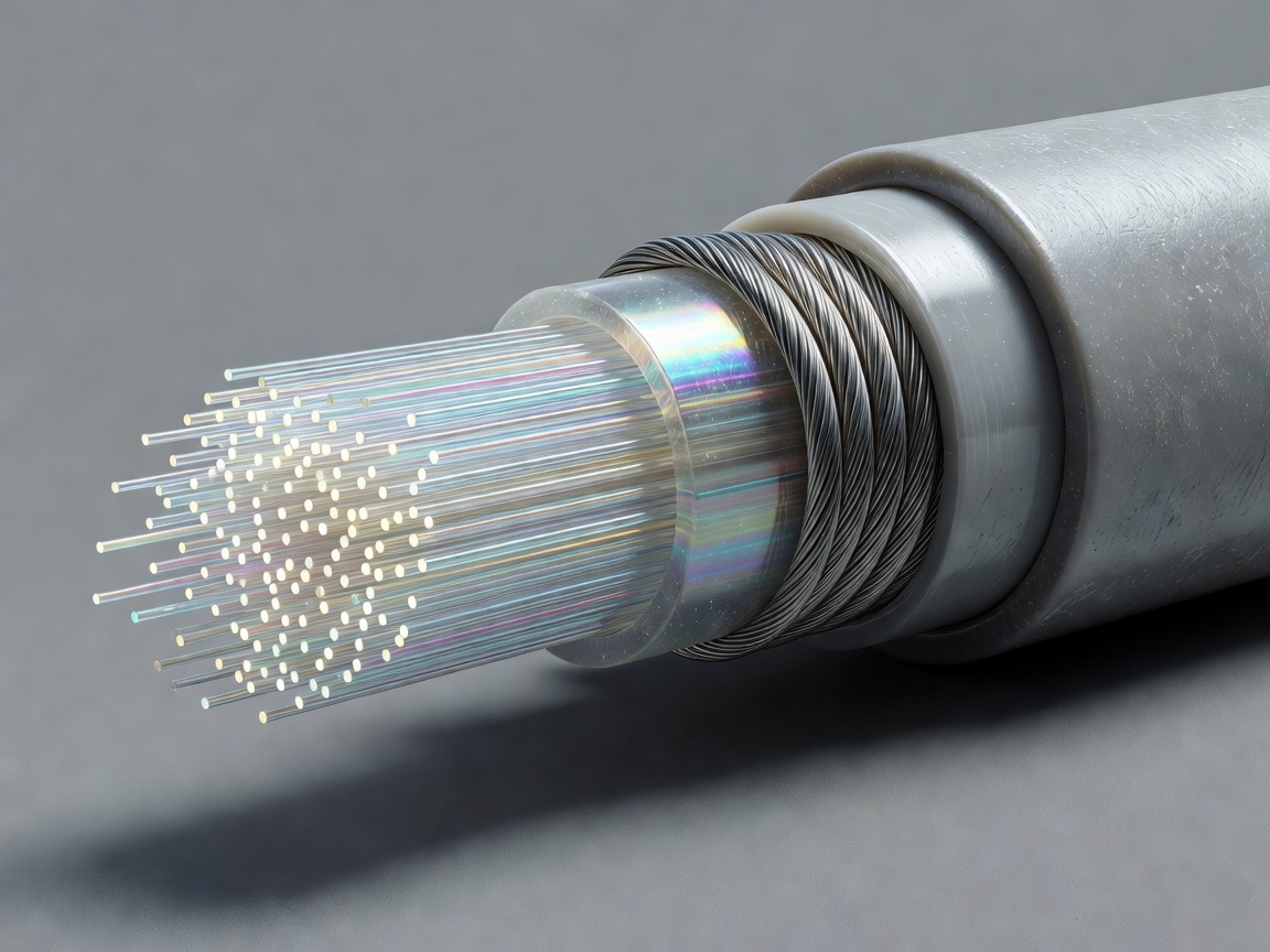
The heart of a fibre-optic cable is a set of glass fibres. Each fibre guides light, and changes in that light encode information. Glass offers a high-capacity medium with low attenuation, but it is not designed to be handled naked in the open sea. The fibres are arranged within a core and surrounded by materials selected to keep them stable, protect them from stress and accommodate the way a long cable is manufactured, loaded and laid.
It helps to imagine a bundle of delicate drinking straws carrying flashes of light, except the “straws” are microscopic glass waveguides and the signal is managed with optical equipment at either end. A fibre does not need a separate electrical wire for every conversation. Multiple wavelengths and transmission techniques let systems carry substantial traffic through the same physical medium.
Fibre counts and system capacity depend on the system design. The cable itself is one part of a broader chain involving terminal equipment, power feeding, repeaters where needed and connections into terrestrial networks. A strong cable cannot compensate for poorly designed terminal interfaces, just as good optical equipment cannot make a mechanically damaged fibre work.
Power along the route
Long submarine systems may include repeaters that amplify or regenerate optical signals along the way. These devices require power. A conductor incorporated into the cable carries direct current from the terminal power-feeding equipment, completing an electrical circuit through the system. Insulation separates that conductor from the surrounding sea and other cable elements.
That power arrangement is a useful reminder that “data cable” does not mean “signal only.” The wet plant—the equipment installed underwater—may combine optical pathways, electrical power and mechanical structure. Design teams consider voltage, current, system length, repeater placement and the electrical behavior of the whole route. Power feed equipment at a landing station is therefore part of the engineering story, even if it is far from the beach where the cable first becomes visible.
The conductor’s material and dimensions are chosen to suit the system. It is not simply a generic wire placed inside a tube. It has to be manufacturable, reliable over long distances and compatible with the insulation and surrounding components. Power is fed with carefully managed arrangements; the ocean is not used as an informal substitute for a properly designed circuit.
Strength, sealing and protection
Surrounding the functional core are layers that can include metallic barriers, water-blocking materials, insulating compounds and strength members. Their exact arrangement varies by cable type and manufacturer. Together, they manage pulling forces, protect against water ingress, preserve the conductor’s insulation and keep the fibres within acceptable mechanical limits.
Armour wires are particularly visible in a cutaway, but armour is not a universal, identical shell along every kilometre. In shallow water, near shore, or in areas with greater exposure to anchors and fishing activity, additional armour can provide useful protection. Deep-water cable may use a lighter construction because the risk profile and installation conditions differ. Heavier construction affects handling, storage, laying tension and the equipment needed to install it.
This is a trade-off rather than a ladder where “more armour” is always better. A design must give the cable enough protection for its expected environment while remaining practical to manufacture, transport and install. Route data and risk assessments inform where cable types change. Transitions are engineered components of the route, not arbitrary cuts made at a convenient point.
A cable’s layers are decisions made visible: each one answers a particular optical, electrical or mechanical question.
Repeaters and branching units
Repeaters are pressure-resistant optical devices placed along systems where signal amplification is required. Their location follows engineering calculations about optical performance, power budget and system length. The repeater is joined into the cable system through factory-made assemblies designed for the underwater environment. It is not a miniature data centre; its function is specific, and its operation is planned as part of the full route.
Some systems also use branching units, which connect a main trunk to another cable segment or destination. Branching can increase route flexibility and connect additional landing points, but it introduces design and operational considerations. The network planner has to understand how traffic may flow, what portions of the system can be isolated for repair and how branches affect power and optical design.
Landing stations house the shore-end equipment that feeds power, transmits and receives optical signals, monitors system behavior and connects to terrestrial networks. The marine cable, repeaters, branching units and terminal stations form one engineered system. A useful diagram should show how these pieces relate rather than suggesting that the cable is a self-contained internet connection.
From factory to ship
Manufacturing is followed by testing, loading and careful stowage aboard a cable vessel. Cable is arranged in large tanks or carousels so it can be paid out under controlled conditions. Bends, tension and handling practices matter: a fibre system can tolerate the intended installation loads, not unlimited force or careless treatment. The vessel crew, installation engineers and shore teams coordinate the operation around the route plan.
At the landing, shore-end cable may be designed differently from a deep-sea section. It must pass through a coastal environment, reach a beach manhole or duct and connect safely toward the landing station. A cable’s design is thus a sequence of locally appropriate constructions joined into a continuous system.
For additional technical context, consult the International Telecommunication Union’s recommendations, including the G.971 family on submarine cable systems, and the International Cable Protection Committee’s guidance. These resources help explain shared engineering vocabulary; the precise design remains specific to the system, route and operating requirements. Next, follow those construction choices across a surveyed seabed in Choosing a Seabed Route.